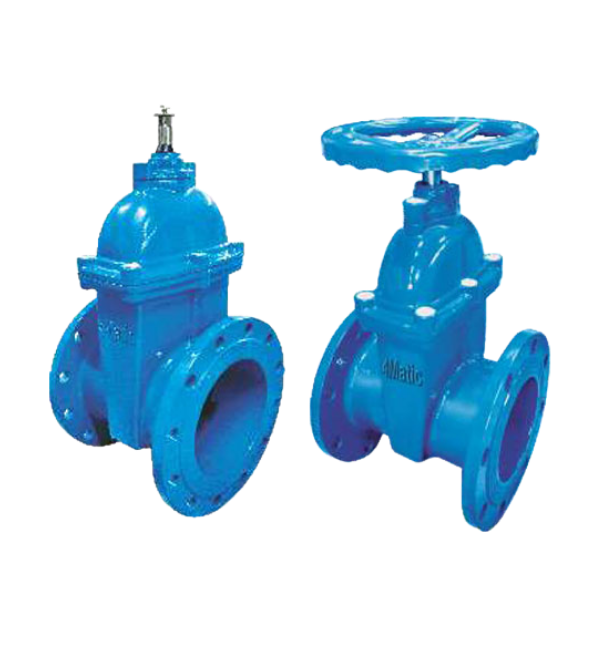
4MSGV Series
Resilient Seated Gate Valve
Description
Resilient Seated Wedge Gate Valve
Applications :
- Chemical applications
- Petrochemical plants
- Oil Refineries
- Power plants
- Hot & Cold water applications
Design Features :
- Design complies to EN1171 / EN1074 / BS5163
- Flanges are drilled to EN 1092-2 / BS4504
- Pressure Rate: PN10/16, (PN25 for DN40-200)
- Test: Body test 1.5 x PN, Seat test 1.1 x P
- Medium: Neutral water, Drinking water, Sewage
- Rolled thread ensure smooth thread edges and low operating torques
- Bonnet bolts are in galvanized carbon steel, SS304 upon reques
- Thrust washer – Brass material, to get more reliable strength and long
- service life when comparing to other factory’s nylon mat
- Body/bonnet connection bonnet gasket fits into a recess in valve bonnet
- preventing it from being blown out by pressure surg
- Wedge nut – made of copper alloy with lubricating ability providing
- optimum compatibility with the stainless steel st
- Bolts sealed with hot met
- Lifting rings
- Operation: Hand wheel, Square cap Gearbox, Actuator
- Manufacturing standard meets BS EN 1074, BS5163.
- Both inside & outside coated with epoxy resin powder.
- Standard colour similar to RAL5005 other colours upon reques
- With rubber dust cover
- O-ring bonnet gasket wraps each bolt to prevent corr
- Completely free and full bore self-clearing & low pressure loss.
- Clockwise closing (CWC) as standar
- Sealing Class A (zero leakage)
Resilient Gate Valve Details :
- Design & Mfg. Std. : BS 5163
- Face To Face : BS 5163
- Flanged End : EN 1092-2
Technical Specification
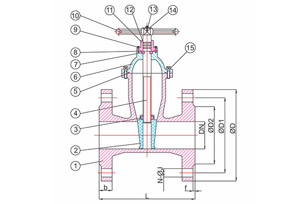
| No. | Description | Material |
| 1 | Body | Ductile Iron |
| 2 | Wedge | Ductile Iron+EPDM |
| 3 | Stem Nut | Brass |
| 4 | Stem | AISI 410 |
| 5 | Gasket | EPDM |
| 6 | Bonnet | Ductile Iron |
| 7 | Locating Ring | Brass |
| 8 | O Ring | EPDM |
| 9 | Bolts | Carbon Steel 8.8 |
| 10 | Hand Wheel/Cap | Ductile Iron |
| 11 | Gland | Ductile Iron |
| 12 | O-ring | EPDM |
| 13 | Nuts | Carbon Steel 4.8 |
| 14 | Washer | Carbon Steel 4.8 |
| 15 | Bolts | Carbon Steel 8.8 |
| TEST PRESSURE | ||
| TESTING | BODY | SEAT |
| HYDRAULIC | 15 kG/CM2 | 11 kG/CM2 |
| Valve Size Inch |
DN | L | ØD | ØD1 | ØD2 | b | f | N-ØJ |
| Tolerance | ±3.3mm | ±2mm | ±2mm | ±3mm | ±1mm | ±1mm | ||
| 2” | (50mm) | 178 | 165 | 125 | 99 | 19 | 3 | 4-19 |
| 2.1/2” | (65mm) | 190 | 185 | 145 | 119 | 19 | 3 | 4-19 |
| 3” | (80mm) | 203 | 200 | 160 | 133 | 19 | 3 | 4-19 |
| 4” | (100mm) | 229 | 220 | 180 | 154 | 19 | 3 | 8-19 |
| 5” | (125mm) | 254 | 250 | 210 | 184 | 19 | 3 | 8-19 |
| 6” | (150mm) | 267 | 285 | 240 | 210 | 19 | 3 | 8-23 |
| 8” | (200mm) | 292 | 340 | 295 | 265 | 20 | 3 | 8-23 |
| 10” | (250mm) | 330 | 405 | 350 | 319 | 22 | 3 | 12-23 |
| 12” | (300mm) | 356 | 460 | 400 | 370 | 24.5 | 4 | 12-23 |
| 14” | (350mm) | 381 | 520 | 460 | 429 | 26.5 | 4 | 16-23 |
| 16” | (400mm) | 406 | 580 | 515 | 480 | 28 | 4 | 16-28 |
| 18” | (450mm) | 432 | 615 | 565 | 548 | 30 | 4 | 20-28 |
| 20” | (500mm) | 457 | 715 | 650 | 582 | 31.5 | 4 | 20-24 |
| 24” | (600mm) | 508 | 780 | 725 | 682 | 36 | 5 | 20-31 |
Installation, Operation & Maintenance Instructions
Storage & Handling :
If the valves are to be stored in the open for sometime, protection should be provided to keep the valves clear of sand and mud. Particular care should be taken to protect the seat. When off-loading valves, care must always be taken. Lifting the valves by use of a hand wheel where fitted is not acceptable. On no account should the valve be handled using the upper flanges. Valves should be lowered gently with care onto wooden battens placed on firm ground clear of mud and water.
Installation :
Operation :
Resilient Seated Gate Valves are designed for On-Off service, regulating or throttling services should be avoided. They comply with both BS EN 1074 parts 1 & 2. The valve is closed by turning the operating element i.e. Cap-Top, Hand wheel or Extension Spindle in a clockwise or anti-clockwise direction, which is confirmed on the Identification label. Once installed operate the valve through its full extent of travel to check for ease of function.
Operation & Application :
Maintenance :
Resilient Seated Gate Valves are designed for underground use with minimum maintenance and requires no lubrication. Differing qualities or properties of the system media will require the valve to be regularly checked for ease of operation, at least every three years.
The valve should be at zero pressure and ambient temperature prior to any maintenance. Maintenance Engineers & Operators are reminded to use correct fitting tools and equipment. A full risk assessment and methodology statement must be compiled prior to any maintenance. The risk assessment must take into account the possibility of the limits of use being exceeded whereby a potential hazard could result. maintenance programmed should therefore include checks on the development of unforeseen conditions, which could lead to failure.
Leaking Gland :
Leaking Bonnet Gasket/Seal :
Body/Bonnet Gasket/Seal Replacement :
- Operate the valve to mid-position.
- Loosen and remove body/bonnet bolting (item 4).
- Operate the valve to the closed position, (rotation of the hand wheel/cap top). When closed, operate the valve a further1/2 to 1 turn, this will break the bonnet seal
- Open the valve to mid-position(rotation of hand wheel/cap top).
- The complete bonnet sub-assembly including the valve wedge can then be lifted off the valve body.
- Remove the body/bonnet seal (item 5) and ensure that both sealing faces are clean and free from damage.
- Fit new body/bonnet joint (smear of silicon grease may be applied for assistance while fitting).
- Fit the bonnet sub-assembly and tighten the bolting evenly, in a diagonal sequence.
- Close and open the valve to check for satisfactory operation.
Stem ‘O’ Ring Replacement :
- Turn off circulating pumps.
- Open the valve fully (the leaking should become minimal or stop completely).
- Slacken the hand wheel or cap top retaining screw. (Item 14)
- Remove the hand wheel or cap top from the stem (tapping underneath with a mallet may be necessary).
- Remove locking pin from the Gland Bush (item 17)
- Unscrew the Gland Bush (Anti-Clockwise). (Item 12)
- Remove the Gland Bush from the stem.
- Fit new stem ‘O’ rings and Gland Bush ‘O’ ring.(A smear of silicone grease may be applied to the ‘O’ rings while fitting). (Items 10 and 11)
- Carefully refit the Gland Bush onto the stem, preventing ‘O’ ring damage.
- Screw the Gland Bush down until tight (Clockwise).
- Fit the locking pin in the Gland Bush
- Fit the hand wheel or cap top.
- Tighten the hand wheel or cap top retaining screw.
- Close and open the valve to check for satisfactory operation.
| No. | Description | Material |
| 1 | Body | Ductile Iron QT450-12 to EN-GJS-450 |
| 2 | Wedge | EPDM Encapsulated Ductile Iron Wedge |
| 3 | Stem Nut | DZR Brass to BS EN 12165 CW602N |
| 4 | Cap screws | Stainless Steel A2 |
| 5 | Bonnet Gasket | EPDM to BS EN 681 |
| 6 | Stem | Stainless Steel 431 S29 |
| 7 | Bonnet | Ductile Iron QT450-12 to EN-GJS-450 |
| 8 | Seal | EPDM to BS EN 681 |
| 9 | Washer | PTFE |
| 10 | O- Rings | EPDM to BS EN 681 |
| 11 | O Ring | EPDM to BS EN 681 |
| 12 | Gland Bush | DZR Brass to BS EN 12165 CW602N |
| 13 | Wiper Ring | EPDM to BS EN 681 |
| 14 | Capscrew/Bolt | Stainless Steel A2 |
| 15 | Handwheel | Ductile Iron QT450-12 to EN-GJS-450 |